

Key Takeaways
Testing an engine control unit is a process of elimination, not a single meter reading. Begin with codes, power, grounds, wiring, and sensor signals before condemning the module.
- Scan for diagnostic trouble codes and save the evidence before clearing anything.
- Confirm battery condition, fuses, ignition feeds, ECU voltage, and ground voltage drop.
- Compare sensor and actuator signals with the vehicle manufacturer’s specifications.
- Inspect connectors, wiring, corrosion, water damage, and communication circuits.
- Replace or reprogram the ECU only after other likely causes have been ruled out.
Understand what the engine control unit does
An engine control unit receives information from sensors and uses it to control several engine functions. The exact strategy varies by vehicle, but fuel delivery, ignition, idle control, and emissions-related decisions are commonly managed electronically. Understanding that relationship makes the question of how to test an engine control unit much less mysterious.
How the ECU manages engine operation
The ECU continuously compares sensor inputs with programmed values, then commands components such as injectors, ignition coils, and throttle systems. A useful overview of these functions appears in this ECU fundamentals guide, but the practical point is simple: a fault in an input, power supply, or output circuit can look like a computer fault.
The difference between an ECU, ECM, and PCM
ECU is a broad term for an electronic control unit. ECM usually means engine control module, while PCM generally refers to a powertrain control module that also manages transmission functions. Manufacturers use these labels differently, so identify the unit by the service information for the specific vehicle rather than by the acronym alone.
Common symptoms of ECU-related problems
Possible symptoms include a no-start condition, intermittent stalling, poor running, an illuminated malfunction indicator lamp, missing communication with a scan tool, or several unrelated systems failing at once. None of these symptoms proves the ECU is defective. A practical engine computer diagnosis guide also begins with visual checks because loose connections and damaged wiring are common causes.
Why wiring and sensors can mimic ECU failure
A shorted sensor can pull down a shared reference circuit, while an open ground can make a healthy ECU appear dead. Damaged harnesses may also interrupt crankshaft, camshaft, injector, or communication signals. Test the circuit at the module and at the component so you know whether the fault is in the ECU, the wiring, or the device being controlled.
Gather the tools and prepare safely
Good preparation prevents many false conclusions and protects expensive electronics. Gather the vehicle-specific wiring information before probing a connector, and work with the ignition switched off unless a test specifically requires power. Stop if a procedure involves airbag circuits, high voltage, or unfamiliar programming equipment.
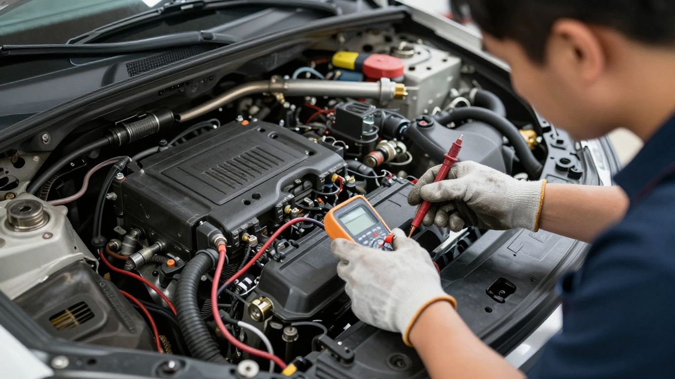
Essential diagnostic and electrical testing tools
At minimum, use a capable OBD-II scanner, a digital multimeter, back-probe leads, a test light suitable for electronic circuits, and basic hand tools. An oscilloscope is valuable for signals that a meter cannot display clearly. A battery charger or support unit can keep voltage stable during extended testing, but it must be used according to the vehicle and equipment instructions.
Finding the ECU and identifying its connectors
The ECU may sit in the engine bay, passenger compartment, kick panel, or beneath a seat. Do not unplug a connector simply because it is accessible. Photograph the installation, note connector positions, and check for locking levers, secondary locks, bent terminals, and signs of moisture before disconnecting anything.
Reviewing wiring diagrams and pinout information
A wiring diagram tells you more than a connector shape can. Confirm terminal numbers, wire colors, splice locations, fuse paths, grounds, reference-voltage circuits, and communication lines. Vehicle-specific information is essential because two similar-looking ECUs can have completely different pin assignments.
Disconnecting the battery and protecting sensitive electronics
Follow the service procedure before disconnecting the battery, especially where an immobilizer, radio code, powered tailgate, or battery-monitoring system is involved. Keep probes from bridging adjacent terminals and never force a test lead into a sealed connector. Even a small mistake can damage a terminal or create a new fault.
Check for diagnostic trouble codes
A scan is usually the least invasive first step. Record what the vehicle reports before touching connectors or clearing memory, then use the codes as clues rather than verdicts. The code identifies a monitored condition; it does not automatically identify the failed part.
Connecting an OBD-II scanner correctly
Use the diagnostic connector specified for the vehicle and connect the scanner with the ignition state requested by its instructions. Record every module that communicates, not only the engine module. If the scanner cannot connect, check the diagnostic connector’s power and ground before assuming the ECU has failed.
Understanding stored, pending, and permanent codes
Stored codes relate to faults that met the module’s criteria during an earlier drive cycle. Pending codes may indicate a condition that has not yet occurred often enough to mature, while permanent codes remain until the vehicle confirms that the repair succeeded. Treat the status as diagnostic context, not as a ranking of severity.
Reviewing live data and freeze-frame information
Freeze-frame data captures operating conditions when a code was set, such as engine speed, temperature, load, and voltage. Live data lets you compare sensor behavior while the engine is cranking, idling, warming up, or being driven. Look for values that are implausible together rather than reacting to one number in isolation.
Clearing codes without losing useful diagnostic evidence
Save or photograph codes, freeze-frame data, and important live readings first. Clearing memory may erase useful clues and can reset readiness monitors, so do it only after recording the evidence and making a repair plan. A subsequent road test should then show whether the original condition returns.
Test the ECU power and ground circuits
Power and ground checks are often more revealing than a visual inspection of the ECU itself. A module may have battery voltage at rest yet lose usable voltage under load, or it may have a ground that appears intact until current flows. Make measurements under the conditions described by the service manual.
Checking battery voltage and charging-system condition
Test battery voltage with the vehicle at rest and while cranking, then check charging voltage with the engine running when safe. Low cranking voltage can cause communication failures and misleading codes. Resolve weak battery or charging-system problems before evaluating module behavior.
Testing ECU fuses, relays, and ignition feeds
Check both sides of each relevant fuse with the circuit energized; a fuse can look intact while power is missing on its supply side. Test relay input, output, and control circuits rather than swapping parts at random. Confirm that the ECU receives constant battery power and the correct switched ignition feed.
Measuring voltage at the ECU connectors
Back-probe the specified power terminals with the connector installed where possible. Compare the reading with battery voltage during key-on, cranking, and running conditions. A reading that is present with no load but collapses during operation points toward resistance in a fuse, relay, splice, terminal, or wire.
Performing a voltage-drop test on ground circuits
Voltage drop measures unwanted resistance while current is flowing. Place the meter across the ECU ground and the battery negative terminal during cranking or another specified load, keeping the probes secure. A higher-than-specified result means the ground path needs investigation rather than an immediate ECU replacement.
Interpreting missing or unstable power readings
Use the wiring diagram to work backward from the ECU terminal toward the battery, fuse box, relay, and ground point. Intermittent readings may result from vibration, heat, corrosion, or a loose terminal. The following comparison helps organize the result before moving to signal testing.
| Finding | More likely area | Next check |
|---|---|---|
| No battery feed | Fuse, relay, splice, or wire | Test continuity and loaded voltage |
| Ignition feed missing | Ignition switch or control circuit | Verify switch output and relay control |
| Ground voltage drop high | Ground strap or terminal | Clean, tighten, and retest under load |
| Power stable but no communication | Network, connector, or module | Check CAN lines and connector condition |
These readings narrow the search without declaring the ECU guilty. If voltage and ground remain stable at the correct terminals, proceed to inputs, outputs, and communication tests.
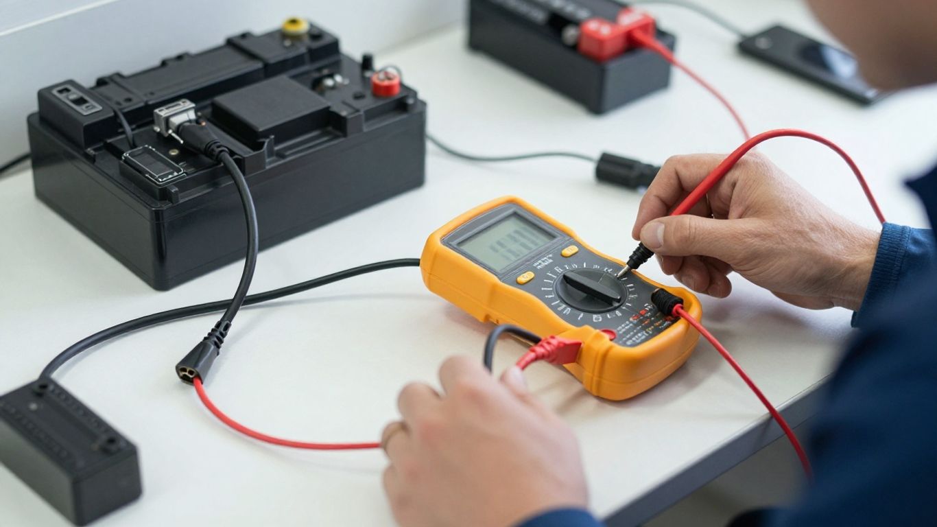
Inspect ECU inputs and outputs
Once the supply circuits are proven, examine what the ECU receives and what it commands. Sensor circuits should be tested without accidentally shorting a reference circuit to ground or battery voltage. The goal is to compare an observed signal with the manufacturer’s expected range and pattern.
Testing sensor reference voltage and signal circuits
Many sensors share a regulated reference supply, signal return, and ground. Check for the reference voltage first, then test the signal while changing the relevant condition, such as throttle position or engine temperature. A missing reference at several sensors can point back to a shared circuit or module protection fault.
Checking crankshaft and camshaft position signals
Crankshaft and camshaft signals are especially important during cranking because the ECU uses them to establish engine position. Check sensor power, ground, air gap where applicable, and signal output. A scope can reveal a distorted or disappearing waveform that a simple resistance test will miss.
Verifying injector and ignition control signals
A noid light, suitable test light, or oscilloscope can show whether injector or ignition control pulses are present. Use the correct method for the circuit; some outputs are ground-switched and should not be tested by applying power directly. If the command is present, investigate the actuator and its supply rather than the ECU.
Using a multimeter, test light, or oscilloscope appropriately
A multimeter is useful for steady voltage, resistance, and voltage-drop measurements. A test light can confirm some loaded circuits, but it must be appropriate for low-current electronic systems. An oscilloscope is better for frequency, duty cycle, and waveform shape, especially when a signal changes too quickly for a meter to display meaningfully.
Comparing readings with manufacturer specifications
Record the test condition beside every measurement: temperature, engine speed, ignition state, and connector position. Then compare it with the exact service-manual specification for that vehicle. Generic internet values can mislead because sensor ranges, pull-up circuits, and actuator strategies differ between models.
Perform advanced ECU and communication tests
Advanced testing is worthwhile when basic power, ground, and circuit checks do not explain the symptoms. It requires more care because network wiring and module programming are easy to disturb. If the fault is intermittent, reproduce it safely while monitoring voltage, communication, and relevant signals.
Checking CAN bus and network communication
A scan tool may show whether other modules can communicate, but network diagnosis also involves checking CAN wiring, termination, voltage behavior, and possible shorts. Follow the manufacturer’s test procedure rather than applying arbitrary resistance targets. One failed module can sometimes disrupt communication with several others.
Looking for damaged wiring, corrosion, or poor connections
Inspect harnesses near brackets, exhaust heat, battery trays, drains, and moving components. Pulling gently on a wire can reveal a broken conductor, while terminal inspection may show fretting, spread contacts, or green corrosion. Repair the underlying connection and protect it from the original source of moisture or abrasion.
Testing the ECU on a bench when appropriate
Bench testing can separate a suspected module from vehicle wiring, but only with the correct breakout harness, pinout, power supply, and test procedure. Do not guess at bench power connections. Some ECUs also require network messages, immobilizer authorization, or programmed configuration before they behave normally outside the vehicle.
Distinguishing software, programming, and hardware faults
A module can have intact hardware but incorrect configuration, corrupted software, or an interrupted programming event. Check for manufacturer service campaigns, software updates, programming history, and relevant configuration procedures. A programming fault should not be treated as proof of failed internal electronics.
Knowing when specialized scan or programming equipment is required
Dealer-level functions may be needed for security access, module setup, relearns, coding, or software installation. Stop before programming if battery support, network stability, or the correct calibration is uncertain. A failed programming session can create a second problem that was not present during the original diagnosis.
A video can help demonstrate probe placement and scan-tool menus, but it cannot replace the wiring diagram and specifications for the vehicle in your bay. Use visual demonstrations for technique, not as a substitute for model-specific procedures.
Confirm the diagnosis before replacing the ECU
Replacing an ECU is a major decision because the replacement may need programming, immobilizer matching, coding, or adaptation. Before ordering one, gather the test results into a clear fault story. This is where a careful ECU troubleshooting reference can provide general background, while the vehicle service manual remains the deciding authority.
Ruling out battery, alternator, and ground problems
Repeat the essential voltage checks after correcting any battery, charging, or ground issue. Confirm that the original symptom and codes have changed as expected. A replacement module cannot compensate for unstable supply voltage, and the same failure may damage or confuse another module.
Comparing test results with service-manual specifications
Do not rely on a reading being merely “close.” Compare it with the correct specification and test condition, including allowable voltage drop, resistance, waveform, or communication state. Write down the result and the expected value so another technician can follow your reasoning.
Checking for water damage, overheating, and connector corrosion
Look for stains, swollen seals, residue, overheated plastic, burnt odor, and corrosion inside or near the ECU enclosure. Find the path that allowed water or heat to reach the module. Replacing the ECU without repairing that path invites another failure.
Deciding between repair, reprogramming, and replacement
Repair may suit a damaged connector or serviceable circuit, while reprogramming may address software or configuration concerns. Replacement becomes more credible only when power, grounds, wiring, inputs, outputs, network communication, and programming requirements have been checked. Match the replacement by part number and vehicle configuration, not appearance alone.
Completing a post-repair verification drive
After the repair, clear codes only after recording them, complete required relearns, and check that all modules communicate. Road-test the vehicle through the conditions associated with the original fault, then rescan for returning codes and confirm readiness status. Keep the diagnostic notes with the vehicle history.
For broader automotive research, even unrelated buying guides such as medium-duty towing or a digital marketing agency should not distract from the same basic habit used here: verify the actual requirement before choosing a solution. Electrical diagnosis rewards that discipline.
Conclusion
A sound ECU diagnosis starts with evidence: scan data, stable power and grounds, verified wiring, credible sensor signals, and communication checks. Work methodically, follow the vehicle-specific specifications, and replace the module only when the test results point to it rather than to a simpler fault elsewhere.
Frequently Asked Questions
Can I test an ECU with only a multimeter?
A multimeter can check power, grounds, voltage drop, and some sensor circuits, but it cannot show every waveform or confirm every communication and programming issue. A scan tool and vehicle-specific service information are usually needed for a complete diagnosis.
What is the first test when an ECU seems dead?
Check battery condition, ECU fuses, constant power, ignition power, and ground voltage drop. Also verify power and ground at the diagnostic connector before concluding that the ECU is not communicating.
Does a fault code prove the ECU has failed?
No. A code normally identifies a monitored condition or circuit. The cause may be a sensor, actuator, wire, connector, power supply, ground, or network problem rather than the ECU itself.
Why does an ECU lose communication?
Possible causes include low voltage, a blown diagnostic fuse, damaged CAN wiring, poor connector contact, another module disrupting the network, software problems, or an internal ECU fault. Test the communication circuit systematically.
Should the battery be disconnected before testing an ECU?
Disconnecting the battery is appropriate for some connector or removal procedures, but not for every voltage test. Follow the service manual and account for security systems, stored settings, and modules that require a specific shutdown procedure.
Can an ECU be repaired instead of replaced?
Sometimes the fault is external and repairable, such as a connector, ground, wiring issue, or configuration problem. Internal repair or replacement decisions depend on the module design, test results, programming requirements, and qualified technical support.
What should be checked after installing an ECU?
Complete required programming, coding, immobilizer matching, and relearns. Then scan all relevant modules, verify live data, road-test the vehicle under the original fault conditions, and confirm that no codes return.